Jan. 23, 2022
Teacher Resources

Originally posted: Jan. 23, 2022
Last edited: 2 years, 2 months ago
We have reached the most interesting section of the python tutorial: Servo Control.
A servo motor is a rotary actuator used for precise control of angular position. Controlling a servo involves sending a modulated square-wave pulse which is known as a pulse-Width-Modulation (PWM). If that pulse is high for 1 millisecond, then the servo angle will be zero, if it is 1.5 milliseconds, then it will be at its centre position and if it is 2 milliseconds it will be at 180 degrees. Generally, a servo requires 3-5 Volts to operate.
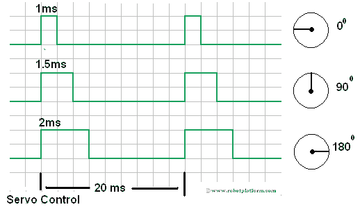
There are two other main factors to be considered while sending a PWM signal to a servo; "Frequency" and "Duty cycle".
Frequency
Servo expects continuous pulses to move or hold its position. Frequency (or repetition time, or cycle time) is the number of times a positive pulse is fed to a servo in a unit time (which is generally measured in seconds); for analog servos, frequency is generally 50 times per second (50Hz) and for digital servos it is 300 times per second (300Hz). The required pulse frequency for few servos may be less, or more depending on the particular model and manufacturer.
Duty Cycle
"Duty cycle" is the width of positive pulse (square wave) and a deciding factor for a servo's angular position. For example, if you have a servo with 180° turn, then 90° is the center position of the servo with 0° being minimum, and 180°, being the maximum. For example, in our servo code, 2% duty cycle corresponds to 0 degrees and 12% duty cycle corresponds to 180 degrees.
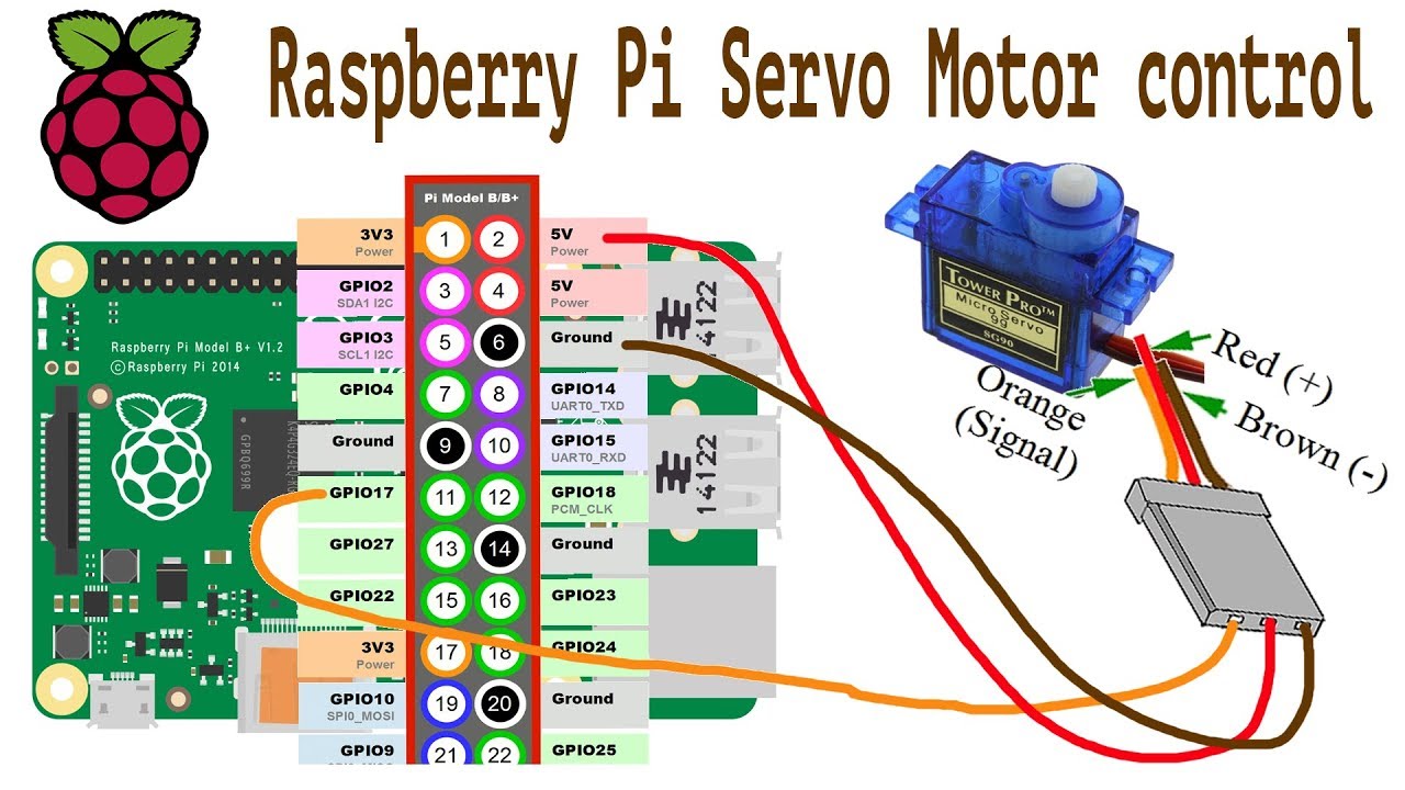
Servo motors generally come with three pin sockets attached. The red and brown sockets supply power (positive to red) and the third yellow or orange socket is for the control signal. To link the socket to the breadboard, use the male-to-male jumper wires.
In our example, we will be connecting pin 11 from a Raspberry Pi to the control signal of the servo.
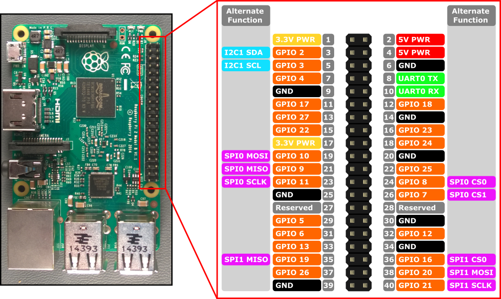
GPIO pins are General Purpose Input/Output digital pins which means they can have two states, off or on. They can have a direction to receive or send current (input, output respectively). Controlling a GPIO pin with Python is accomplished by first importing a library of pre-written code. The most common library is RPi.GPIO.
A Raspberry Pi has 40 pins and in this lesson, we name the pins by counting them from left to right.
To familiarize yourself with the servo wiring check this exercise here.
Now you will learn how to write the Python code to control a servo motor using the Raspberry Pi provided to you by your instructor. Follow simple steps here.